Archive:Router Lift
| Router Lift Release status: experimental [box doku] | |
|---|---|

| |
| Description | The Router lift is an under workbench electronic lift which can position router cutters at specific depths for accurate cuts. |
| Author(s) | Alex
Juan Rainer (AliG) |
| Last Version | 1.0 (22.04.22) |
The router lift project aims to design an under table router lift driven by a NEMA stepper motor. With an open frame design and universal mounting plate, different models can be swapped in and out to allow for a selection of any router a user may want. With a dial driven control system, precise depth cuts can be made in wood and aluminium without the need for depth measurement or manual positioning of the router.
Hardware
Mechanical
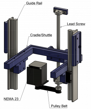
Two parallel guide rails with a circular profile provide linear support as the lift travels up and down 🔗
The lift is driven by a trapezoidal lead screw with a 12mm diameter and lead of 4mm supported at each end by a rotary bearing 🔗
The lead screw is driven by NEMA 23 stepper motor via a pulley belt using a HTD-3M tooth profile 🔗
The Guide rail and lead screw are spaced by fabricated mounting points (currently 3D printed PLA, milled aluminium is planned)
The Cradle or shuttle consists of a frame which can hold a mounting plate, a housing for the lead screw nut and housing for the linear guide runner which traverses the guide rails. This is also fabricated (3D printed for fitment, MDF replica for load testing and milled aluminium for final model).
Finally, the external frame provides housing for all mechanical components, it will allow space for a minimum vertical travel of 100mm and is planned to support routers of up to 310mm width (including distance between tips of handles). Currently this is in the form of MDF board but is planned to be constructed from milled aluminium.
Electronic
The electronic hardware used for the project consists on the following blocks/modules: ESP32 WROOM Dev Kit Microcontroller where the Software is running. It has several IO Pins all of them can act as an interrupt It has also Bluetooth and WLAN Connectivity
I2C Display
Motor Controller
At the moment using Pololu A4988:
Future following evaluation Board will be implemented to be able to drive more current and fine tuning the Motor Controlling through SPI Interface
🔗
Encoder: Incremental Encoder to read the user input
Base PCB: created with Kicad and versioned in Github 🔗
Software
The software is versioned and documented in Github 🔗
Actual dependencies:
adafruit/Adafruit SH110X @ ^2.1.4
To control the I2C Display
waspinator/AccelStepper @ ^1.61
To control the stepper motor speed and acceleration curves
igorantolic/Ai Esp32 Rotary Encoder @ ^1.4
To read the incremental encoder of the user input
mathertel/OneButton @ ^2.0.3
To read the button and allow multiclick interaction
Documentation
Costing
The first round of mechanical component acquisition File:Bill of materials 08 04 22 - Variation 1 - 12 16.pdf
Testing
Initial testing report of first prototype File:Router Test Report 02 05 2022.pdf
Cradle stability testing report File:Cradle Stability Testing 05 05 2022.pdf
Second test report of first prototype File:Router Test Report 09 05 2022.pdf
Third test of first prototype File:Router Test Report 09 06 2022.pdf