ErgoDash
| ErgoDash Release status: beta [box doku] | |
|---|---|

| |
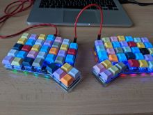
| Description | Building our own nice looking keyboard in two more or less ergonomic pieces |
| Author(s) | Uli (Tamás & Uli) |
| Last Version | 0.9.0 (17.10.2019) |
| Platform | QMK |
| License | ErgoDash is under MIT License |
| Download | https://github.com/omkbd/ErgoDash |
Introduction
This keyboard is the result of frustration of not getting the keyboard we want because it was either too expensive or not available or both. So we decided on building our own. Since we couldn't find an open source layout for the very much desired orhtolinear "Preonic" from OLKB https://olkb.com/preonic, we found the Ergo Dash to start with since the PCB designs are available under MIT license. Probably inspired by the ErgoDoxEz, the ErgoDash is an open source project and can be found here https://github.com/omkbd/ErgoDash.
Other custom keyboard layouts and manufacturers can be found here:
 - Ergodox EZ https://ergodox-ez.com/
 - Planck EZ https://ergodox-ez.com/pages/planck
 - OLKB https://olkb.com/
Parts
Order list: https://docs.google.com/spreadsheets/d/1jseLgmKsGSOt070vr_fO8ZmJpHGX4H3fttUJ9bLBZD8/ (complete shopping list or BOM will be added soon)
Still have lots of parts and a couple of PCBs lying around. So if you are interested in building your own ergodash keyboard, feel free to contact me in slack...
Case
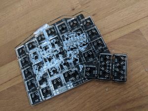
The case has to be manufactured (e.g. lasered out of acrylic glass) and consists of 3 parts:
- top layer (between actual switches and PCB
- bottom layer (lower side of PCB)
- microcontroller panel (covers the arduino and TRRS connector)
Assembly
1. Order PCB, electronics parts, cables, case material (e.g. acrylic glass) and screws
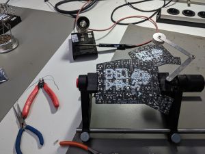
2. Solder electronics onto bottom side of PCB
3. Build Case (e.g. laser acrylic glas which looks nice)
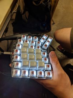
4. Attach and solder keys and backlight LEDs to top side of the PCB between top case and PCB
5. Assemble full case by using small screws and spacers
6. Upload firmware & connect keyboards
7. Finish and fine-tunig (e.g. silicone rubber feet on bottom) or artisan keycaps
Some design choices should best be made before ordering or manufacturing the case
- backlight LED color (Tamás chose white and Uli chose blue for example) - choice of LEDs might have an impact on the resistors too => please check
- single (1U) or double (2U) thumb switches
- position of lower middle switch (inline or offset with the row above)
Also a pretty good description can be found here: https://github.com/omkbd/ErgoDash/blob/master/Doc/build-en.md
Debugging
Soldering resistors and diodes
Please check that you have soldered all components onto the PCBs. Make sure to count them and to be on the safe side, let someone else have an unbiased look at it.
Keys and backlight LEDs
During assembly of keys and backlight LEDs, it should be checked quite often (e.g. after each row or so) that the keys have contact (multimeter in beep mode) and the LEDs glow (check right polarity first and then attach the board connectors on top with a PSU - use very carefully in C.C mode). It is very painful when you make mistakes here, because it could mean that you have to disassemble many parts again to reach the defective areas
Bottom WS2812 LEDs
If not all bottom WS2812 glow, use a multimeter to check if all voltage and ground pins are soldered properly and if the signalling between the LEDs is connected.
Firmware
We used the 333fred firmware layout of the ergodash.
firmware can be found here: https://github.com/qmk/qmk_firmware/tree/master/keyboards/ergodash
Open Issues
Uli still has some open issues with the backlight of his left hand part of the keyboard, which tends to get darker and darker - after about a minute or two it is completely dark. Maybe it is the result of some leakage current by soldering not properly. After reconnecting the keyboard, the backlight glows at full intensity again, but becomes darker over time as described before.


