Archive:LightsOut: Difference between revisions
(version 2.0 planning for the new space) |
m (Vrs moved page LightsOut to Archive:LightsOut) |
||
| (3 intermediate revisions by 3 users not shown) | |||
| Line 1: | Line 1: | ||
{{outdated}} | |||
{{project | {{project | ||
|name = LightsOut | |name = LightsOut | ||
|status = | |status = obsolete | ||
|image = LightsOut_prototype.jpg | |image = LightsOut_prototype.jpg | ||
|description = Light control for the space | |description = Light control for the space | ||
| Line 55: | Line 57: | ||
== Version 2.0 == | == Version 2.0 == | ||
For the [[New Space|new space]], we'll have to implement a new light control system. This is the rough plan: | For the [[Archive:New Space|new space]], we'll have to implement a new light control system. This is the rough plan: | ||
* 9 light zones (CFL lights), spread over 3 "rooms" | * 9 light zones (CFL lights), spread over 3 "rooms" | ||
* 1 12 channel DMX switchpack | * 1 12 channel DMX switchpack | ||
Latest revision as of 15:58, 10 September 2022
| LightsOut Release status: obsolete [box doku] | |
|---|---|

| |
| Description | Light control for the space |
| Author(s) | tiefpunkt |
LightsOut should eventually control the lights in the space, from normal lamps to fancy RGB stripes.
Connectivity
LightsOut is part of the MuMaBus. Lights will probably be availabe in the MuMaBus tree under "mumalab/room/lights/#"
Initial Prototype
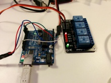
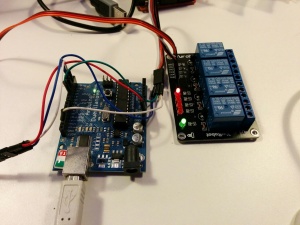
A small prototype using a relay board and Arduino led to the creation of the MuMaBus Node. The arduino was running Firmata, and pins were directly controlled from software. The python code running on a PC connected to MuMaBus and commands were interpreted correctly. A HTTP interface using MQTT-over-WebSockets was built [1]
Hardware
Currently, LightsOut nodes are planned on Arduinos, which require some sort of embedded PC (such as RPi) to handle MuMaBus communications. Eventually, the Arduinos might be removed and the control hardware such as relay boards are connected directly to the RPi.
Arduinos should use bitlash instead of Firmata for future prototypes.
Switching Node
A node with a set (8 or 16) relais. Will use ready made relay boards with 8 relays. Plan for the future is to connect those using shift registers and SPI, but for now, they'll controlled directly by an Arduino.
RGB Node
A node controlling RGB LEDs, such as the RGB strip currently in the space. The plan is to use WS2801 controllers (datasheet, Cheapish online store, otherwise eBay) to control multiple strips using one RGB node with a SPI-like interface.
RCSwitch Node
A node controlling remote controlled power sockets via RCswitch. Directly connected to the RPi
Status
Nodes
- 1 RCswitch node connected to the status RPi
Lights
| Name | Type | Topic | Notes |
|---|---|---|---|
| Whiteboard | RCswitch | mumalab/room/lights/whiteboard/state | switched on and off with the space status |
| Hanging Lights | RCswitch | mumalab/room/lights/hanging_lights/state | switched on and off with the space status |
| Chandelier | RCswitch | mumalab/room/lights/chandelier/state | switched on and off with the space status |
Rules
Currently only via indiviual Python scripts
- Switch whiteboard light tube and hanging lights on and off in reponse to space status changes.
Version 2.0
For the new space, we'll have to implement a new light control system. This is the rough plan:
- 9 light zones (CFL lights), spread over 3 "rooms"
- 1 12 channel DMX switchpack
- USB->DMX interface
- RPi (or similar) with openHAB
- Input device to interface with lightswitches (push buttons?) in the space
USB->DMX interface
Probably a uDMX interface


