CNC router build
| CNC Mill Release status: experimental [box doku] | |
|---|---|
| Description | |
| Author(s) | Tarwin |
| Last Version | v0.1 |
We want to use the big-ass CNC portal Thomas rescued from the trash to build a CNC router.
Goals
- Mill Aluminium!
- route PCBs
- be open for extensions, easy tool change
Hardware
Motor System
X & Y Motors
Z Motor
- Berger-Lahr VRDM368 50LNBOB
- brake needs 24V to loosen, works.
Motor controllers
- 3x JMC 3M860
Power supplies
- 3x 70V 400W from China
Motor cabeling
Z axis
- 1 = U
- 2 = V
- 3 = W
- 4 = NC
- 5 = break brown cable
- 6 = break white cable
X axis
- 1 = U
- 2 = V
- 3 = W
- 4 = NC
- 5 = NC
- 6 = NC
Endstops
X & Y
- Type unknown
- Seems to be an Solid-state Auto Switch, not just a Reed sensor, same pinout as the SMC
Z
- SMC D-F9H (datasheet) (Solid-state Auto Switch, works like a PNP transistor)
- Omron EE-SX870p Photomicrosensor (datasheet)
Electrical
- all endstops can be driven with 5 to 24V.
- Pinout is: brown: VCC / blue: GND / black: Signal
- Pinout on X: brown: VCC / green: GND / white: Signal
- all have a red led which goes out if they sense something
- Some input here
Endstop RJ45 connector
- - Signal Z-
- - Signal Z+
- - VCC (5-24V) (Brown)
- - Signal Y-
- - GND (Orange)
- - Signal Y+
- - Signal X+
- - Signal X-
List Left Sub D 25 Pol connector
- - 1 Red Cable Driver X
- - 2 Black Cable Driver X
- - 3 Green Cable Driver X
- - 4 Gray Cable Driver X
- - 5 Red Cable Driver Y
- - 6 Black Cable Driver Y
- - 7 Green Cable Driver Y
- - 8 Gray Cable Driver Y
- - 9 Red Cable Driver Z
- - 10 Black Cable Driver Z
- - 11 Green Cable Driver Z
- - 12 Gray Cable Driver Z
- - 13 Free
- - 14 Endstop Blue Cable RJ45=4 -> Signal Y-
- - 15 Endstop Blue/White Cable RJ45=5 -> Signal Y+
- - 16 Endstop Orange Cable RJ45=2 -> Signal Z+
- - 17 Endstop Orange/White Cable RJ45=1 ->Signal Z-
- - 18 Endstop Green Cable RJ45=6 ->Signal Y+
- - 19 Endstop Green/White Cable RJ45=3 ->VCC (5-24V)(Brown)
- - 20 Endstop Brown Cable RJ45=8 -> Signal X+
- - 21 Endstop Brown/White Cable RJ45=7 -> Signal X-
- - 22 Free
- - 23 Free
- - 24 Free
- - 25 Free
List Right Sub D 25 Pol connector
- - 1
- - 2
- - 3
- - 4
- - 5
- - 6
- - 7
- - 8
- - 9
- - 10
- - 11
- - 12
- - 13
- - 14
- - 15
- - 16
- - 17
- - 18
- - 19
- - 20
- - 21
- - 22
- - 23
- - 24
- - 25
Software
Sub-projects
Fix up portal
- The portal needs to put together and fixed up
- Put portal together, replace belt - done
- identifiy / Test endstops - done
- Build portal frame - in progress (Thomas E)
- Try Z axis brake - done
Frame and table
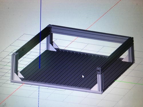
- The X Axis is raised, the linear bearing runs far above the tool head. This implies a high center of gravity.
- Frame needs to be very stable
- Old workbench?
First draft:
Tool head
- needs to be powerful (Aluminium) and precise (pcbs)
- Find matching Spindle with driver and cooling - done
- Bought this: 2.2kw wassergekühlte Frässpindel
- This can be controlled manually on the inverter or over serial.
- needs its own fuse and a fault current fuse (FI Schutzschalter)
- Technical data:
- 2.2kW / 8,000 - 24,000 RPM
- ER20 spring collets (Spannbuchsen)
- Driver: HY02D223B
- water cooled
Software & Controller
- What will tell the drivers what to do? PC/parallel port, Mikrokontroller, old CNC hardware, ...
- Hardware? What do we need?
- Main page for this: CNC_router_software_eval
Pictures
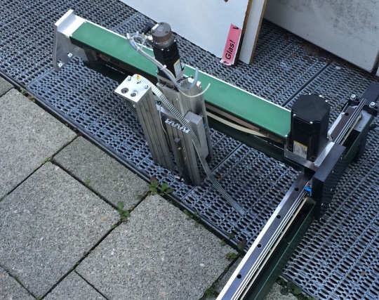
Last picture of the portal before it ware put apart and brought to the space


