CNC router build
| CNC Mill Release status: experimental [box doku] | |
|---|---|
| Description | |
| Author(s) | Tarwin |
| Last Version | v0.1 |
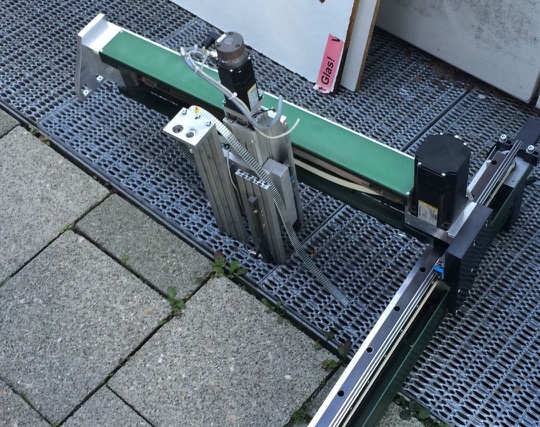
We want to use the big-ass CNC portal Thomas rescued from the trash to build a CNC router.
Goals
- Mill Aluminium!
- route PCBs
- be open for extensions, easy tool change
Hardware
Motor System
X & Y Motors
Z Motor
- Berger-Lahr VRDM368 50LNBOB
- brake needs 24V to loosen, works.
Motor controllers
- 2x JMC 3M860 -- Manual: File:3M860.pdf
- 1x Another Stepper driver, different from the JMC 3M860 with a different cable configuration, which was bought as a replacment for a faulty JMC3M860 File:CWD3M860.pdf
Power supplies
- 3x 70V 400W from China
Motor cabeling
Z axis
- 1 = U
- 2 = V
- 3 = W
- 4 = NC
- 5 = break brown cable
- 6 = break white cable
X axis
- 1 = U
- 2 = V
- 3 = W
- 4 = NC
- 5 = NC
- 6 = NC
Endstops
X & Y
- Type unknown
- Seems to be an Solid-state Auto Switch, not just a Reed sensor, same pinout as the SMC
Z
- SMC D-F9H

- Omron EE-SX870p Photomicrosensor (datasheet)
Electrical
- all endstops can be driven with 5 to 24V.
- Pinout is: brown: VCC / blue: GND / black: Signal
- Pinout on X: brown: VCC / green: GND / white: Signal
- all have a red led which goes out if they sense something
- Some input here
Endstop RJ45 connector
- - Signal Z-
- - Signal Z+
- - VCC (5-24V)
- - Signal Y-
- - GND
- - Signal Y+
- - Signal X+
- - Signal X-
Handwheel
Bought from AliExpress, [page]
-
Pedant
-
Pinout
-
back
Pinout:
    1  GND
    2  +5V
    3  A+
    4  B+
    5  A-
    6  B-
    7  Emergency Stop (pin 1)
    8  Emergency Stop (pin 2)
    9  LED+
   10  LED-
   11  COM
   12  X
   13  Y
   14  Z
   15  4
   16  x1
   17  x10
   18  x100
Encoder Wheel
The wheel needs a +5V power supply, and outputs a slightly lower voltage on A+/B+/A-/B-. One step of the wheel goes through a full cycle. This is not a regular switch, so no connection can be measured.
It is a rotary encoder with grey code. Need to check 4 bit or 2 bit. Some arduino Librarys are available https://github.com/brianlow/Rotary Demotape (talk)
Emergency Stop
This is a standart Mushroom Knot
Inside are 2 simple normally closed switch.
one is connected to the control unit to stop the program
the second one is connected with the power switch so if pressed the Power for motors and spindle will be switched off ( power for the control unit stay on)
The two switches are needed for a two channel emergency stop. Cut off all energy with two separated contactor (Schütze). Demotape (talk)
LED
A red LED, 20mA standard current drive.
Selection Switches
These switches are connected through the "Enable" button on the left. No signal is received unless the button is pressed.
The X, Y, Z and 4 pins are connected to COM when the respective axis is selected, and the enable switch pressed.
The x1, x10 and x100 pins are connected to COM when the respective speed is selected, and the enable switch pressed.
Connection to Linux CNC
https://github.com/DylanVanAssche/LinuxCNC-Pendant/blob/master/LinuxCNCPendant.ino
The hand wheel is connected to an arduino.Hat With a Atmega 32u4 Microcontroller(Arduino Leonardo, Arduino Pro mini)? The Arduino is like as a keyboard and send only key presses. Demotape (talk)
Controller
Manuals for CNC Controller:
- File:CNC Controller.pdf Handsteuerung
- File:CNC Controller use in Mach3 Mill and Pin-Out.pdf Description of Pins of the controller board and how to operate it within Mach3 Mill
- File:Controller Board Relay Output Wiring.pdf Information for connecting the spindle to a relay and the controller
- File:Wiring for Endstops and Emergency Stop.pdf How to wire the endstops and the emergency stop
- File:PCI-Parallel-setting.pdf windows settings for using the parallel port
Spindle
Connector Pins = Cable
1 = 1 2 = 2 3 = 3 4 = PE
Cable = controller side
Cable 1 = U Cable 2 = V Cable 3 = W PE Cable = E
Software
Sub-projects
Fix up portal
- The portal needs to put together and fixed up
- Put portal together, replace belt - done
- identifiy / Test endstops - done
- Build portal frame - done
- Try Z axis brake - done
- Build Table for better stability and moveability - done
- Build exhaust for spindle - in progress ( one printed part broke need redesign more stable and print again ) pipe and tube ared ordered
- Create an holder for Water Tank + Cover for Power and pipe insert
- Front plate - in progress
- Movement Mechanic for the front/top Cover - in progress
- milling flat the area of the Vice
- create holder to be able to fix the vive in place ( in perfect angle )
- Measure and drill the last holes of the spindle holder
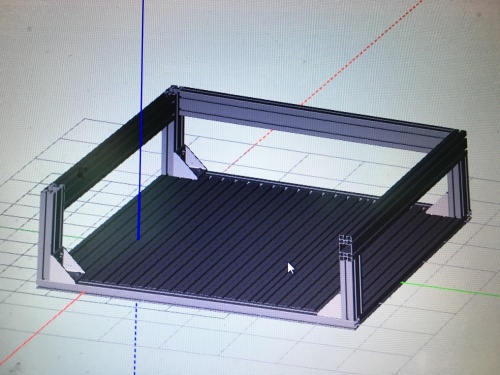
Frame and table
- The X Axis is raised, the linear bearing runs far above the tool head. This implies a high center of gravity.
- Frame needs to be very stable
- Old workbench?
First draft:
Tool head
- needs to be powerful (Aluminium) and precise (pcbs)
- Find matching Spindle with driver and cooling - done
- Bought this: 2.2kw wassergekühlte Frässpindel
- This can be controlled manually on the inverter or over serial.
- needs its own fuse and a fault current fuse (FI Schutzschalter)
- Technical data:
- 2.2kW / 8,000 - 24,000 RPM
- ER20 spring collets (Spannbuchsen)
- Driver: HY02D223B
- Manual of the driver
- water cooled
Software & Controller
- What will tell the drivers what to do? PC/parallel port, Mikrokontroller, old CNC hardware, ...
- Hardware? What do we need?
- Main page for this: CNC_router_software_eval
Pictures
Last picture of the portal before it ware put apart and brought to the space


