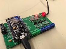
Multiswitch
| YT.GL MultiSwitch Release status: beta [box doku] | |
|---|---|

| |
| Description | PCB with 4 outputs (mosfets), 2 inputs and a dc-dc 7V-32V to 5V converter |
| Author(s) | German (c22) |
| Last Version | 1.1 (10.03.2020) |
Why
The original idea was to use relais and a nodemcu to control the locking unit of a user box. While it worked, it had a couple of big drawbacks (e.g. faulty relais, lot of wires for power distribution and so on...). The idea for the better version using mosfets was brought up by Paul who is using mosfets to control valves for the wasserschaden project.
How
A prototype exists in the form of a quickly jumper-wired setup that has been in "production" for a couple month. I took the requirements & learnings from this setup and created a first version of the PCB schematic in EasyEDA. Throughout the development process, I discussed my ideas with Paul who helped with lot of ideas and recommendations for the technical design. Once the final schematic was ready, I manually routed all the parts for the PCB in order to get the design that made most sense.
Production
The PCB was produced by JLCPCB and all SMD parts were assembled by JLCPCB. A board that comes from the factory just needs all connectors and the pin headers to be soldered.
Versions
- 1.0 initial release
- 1.1 track width increased, board layout changed to fit on 10cm x 10cm, recommended input changed to 9-24V (max 25V), added 10k pulldown resistors to inputs, changed voltage divider for the buck converter in order to get 5.2V output instead of 4.7V
Known Bugs
- v 1.0 needs pulldown resistors on both inputs to operate properly
