Archive:BreadboardPower: Difference between revisions
m Vrs moved page BreadboardPower to Archive:BreadboardPower |
(No difference)
|
Latest revision as of 12:58, 10 September 2022
| Breadboard Power Release status: beta [box doku] | |
|---|---|
| |
| Description | Simple regulated power supply that can be used on breadboards |
| Author(s) | Simon (SimonRichter) |
| Last Version | 0.1 (2014-11-30) |
| Platform | electronics |
| License | PD |
| Download | File:Breadboardpower-0.1.zip |
 You are visiting an old member project. The information found on "BreadboardPower" might be out of date.
Goal
I'd like to have a simple regulated power supply that can be used on breadboards, providing 5V, 3.3V and a third, adjustable voltage.
Implementation
The board uses an Allegro A4490 triple regulator and a few supporting components.
For each output, the IC realises a switching FET that is activated when a feedback voltage is below 0.8V, connecting the supply input with the output.
The switched voltage is run through an inductor, and further smoothed with a parallel capacitor. An additional capacitor on the input side further stabilizes the system.
When the FET opens, the inductor builds up a reverse voltage, which is caught in a flyback diode.
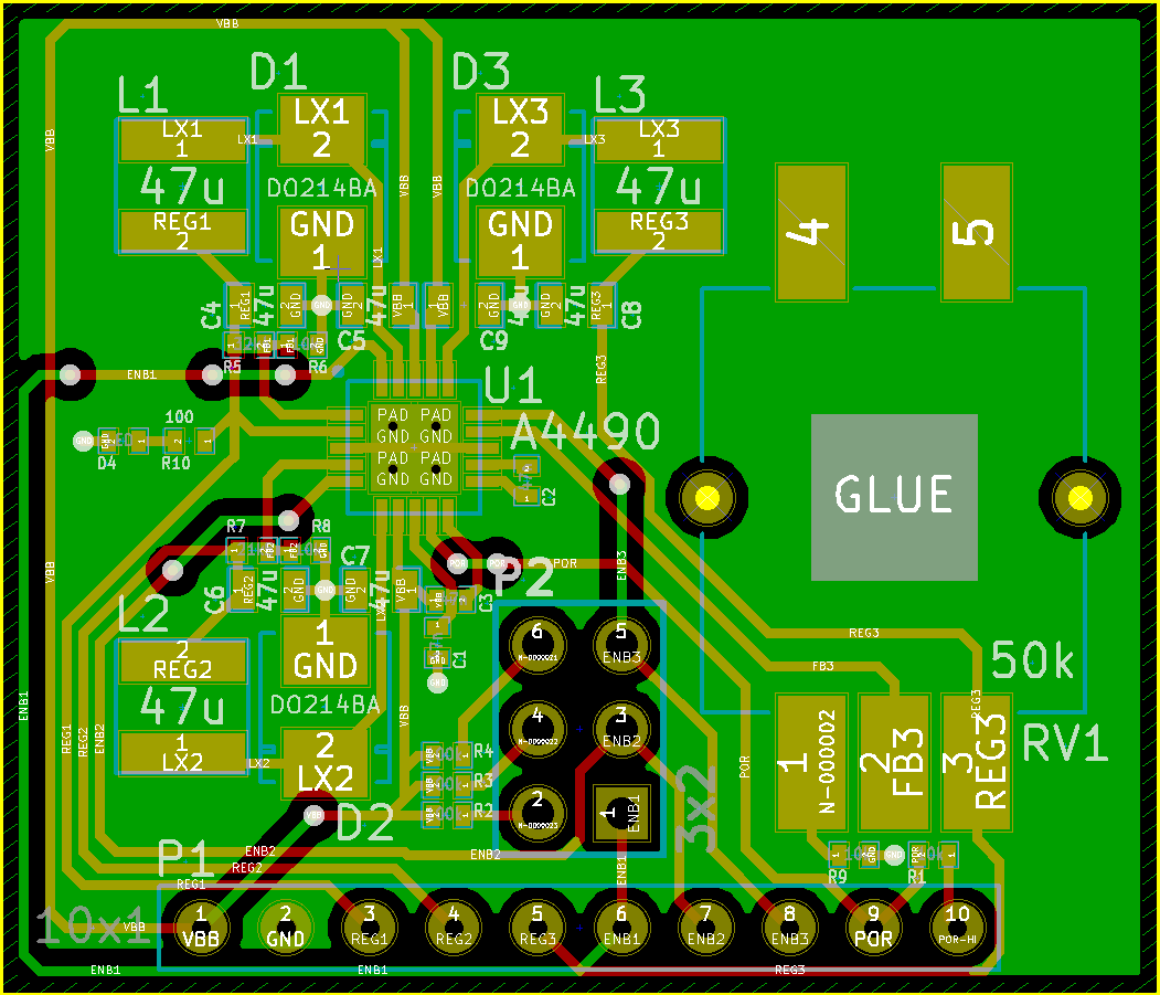
The design attempts to minimize the area covered by the traces running non-continuous signals, in order to reduce EM emissions.
Bill of Materials
| Id | Size | Type | Value | Description |
|---|---|---|---|---|
| C1 | 0402 | 47nF | Power-On Reset Time Constant | |
| C2 | 0402 | 47nF | Charge Pump Capacitor 1 | |
| C3 | 0402 | 47nF | Charge Pump Capacitor 2 | |
| C4 | 0804 | 47µF | Output Filter (1) | |
| C5 | 0804 | 47µF | Input Filter (1) | |
| C6 | 0804 | 47µF | Output Filter (2) | |
| C7 | 0804 | 47µF | Input Filter (2) | |
| C8 | 0804 | 47µF | Output Filter (3) | |
| C9 | 0804 | 47µF | Input Filter (3) | |
| D1 | LSM115J | Flyback Diode (1) | ||
| D2 | LSM115J | Flyback Diode (2) | ||
| D3 | LSM115J | Flyback Diode (3) | ||
| D4 | 0603 | LED | Power LED | |
| L1 | Taiyo Yuden NRG4026T470M | 47µH | Inductor (1) | |
| L2 | Taiyo Yuden NRG4026T470M | 47µH | Inductor (2) | |
| L3 | Taiyo Yuden NRG4026T470M | 47µH | Inductor (3) | |
| P1 | 0,1" | Connector | Bottom Connector, 10x1 | |
| P2 | 0,1" | Connector | Enable Jumpers, 3x2 | |
| R1 | 0402 | 10kΩ | Pull-Up for Power On Reset | |
| R2 | 0402 | 100kΩ | Current Limiter Enable (1) | |
| R3 | 0402 | 100kΩ | Current Limiter Enable (2) | |
| R4 | 0402 | 100kΩ | Current Limiter Enable (3) | |
| R5 | 0402 | 221kΩ | Voltage Divider Upper Half (1) | |
| R6 | 0402 | 42.1kΩ | Voltage Divider Lower Half (1) | |
| R7 | 0402 | 215kΩ | Voltage Divider Upper Half (2) | |
| R8 | 0402 | 68.8kΩ | Voltage Divider Lower Half (2) | |
| R9 | 0402 | 240Ω | Voltage Divider Lower Half (3) | |
| R10 | 0402 | 100Ω | Current Limiter Power LED | |
| RV1 | Bourns PRS11S | 50kΩ | Voltage Divider Upper Half (3) | |
| U1 | Allegro A4490 | Regulator IC |
You can fudge the resistor values to reach different voltages and change the range covered by the potentiometer.
Status
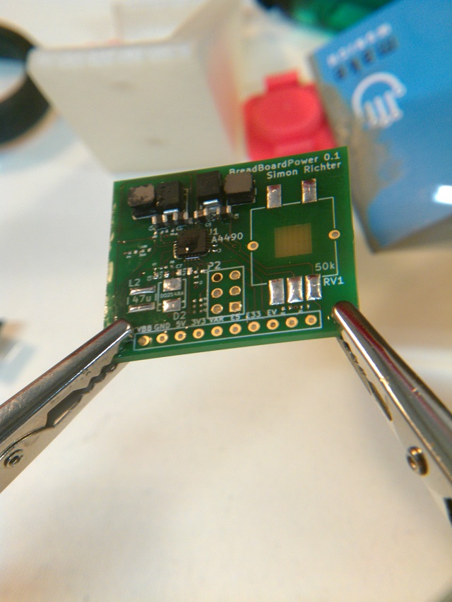
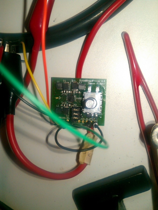
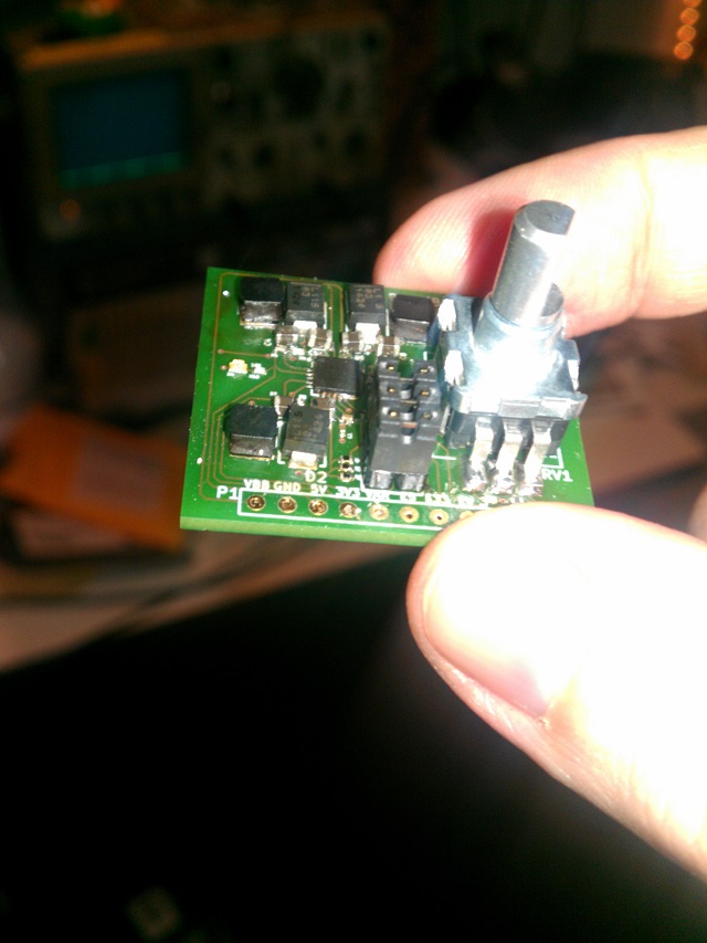
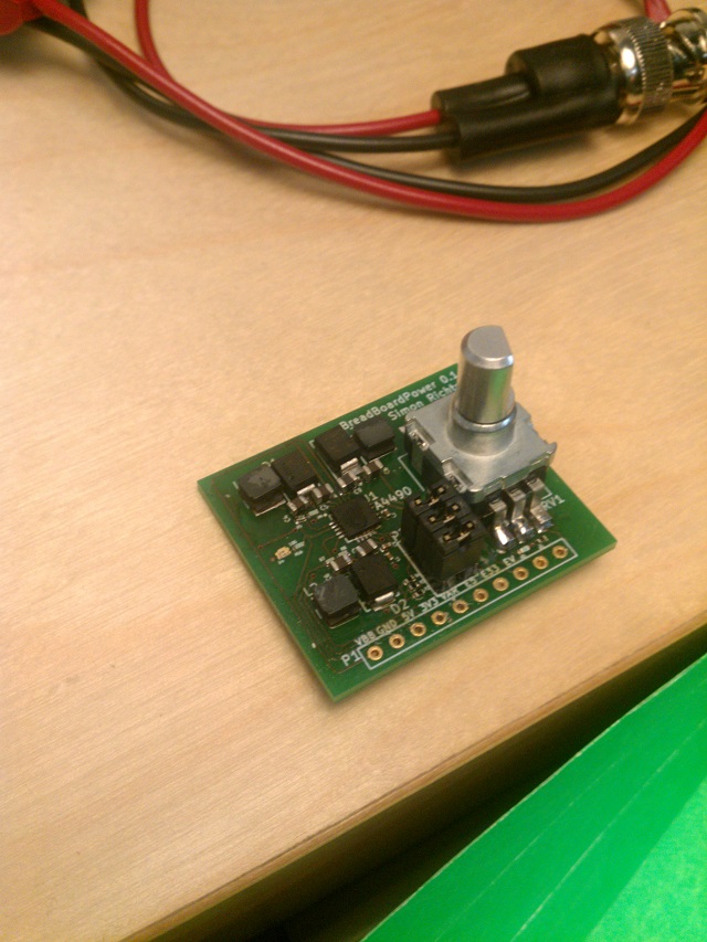
First PCBs have been manufactured, and one has been assembled. It appears to work. Next: testing.
Work in Progress
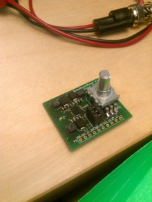
Completed Board
Fingers for Scale
Obligatory Glamour Shot
Layout
Releases
Version 0.1
Bugs:
- The input and output capacitors use a 0603 footprint rather than 0804. 47µF capacitors are not yet available in that size. Still solderable.
- The footprint for the LED is too small. Still solderable.
- The drill size for the potentiometer's mechanical attachment is too small, it should probably be 1.5mm.
- The resistor values given have only a limited range on the variable output; use a smaller fixed resistor for greater voltages
- The two rightmost connections are not labeled
- The current limiting resistors for the enable signals could be placed in line with the enable inputs, so the external circuitry doesn't need a current limiter.
- The traces could be laid out better
