Auduino: Difference between revisions
(Created page with "{{project |name = Auduino |status = experimental |image = |description = Simple Arduino based synthesizer |author = tiefpunkt |usern...") |
(pictures) |
||
| (5 intermediate revisions by the same user not shown) | |||
| Line 1: | Line 1: | ||
{{project | {{project | ||
|name = Auduino | |name = Auduino | ||
|status = | |status = beta | ||
|image = | |image = Auduino01.jpg | ||
|description = Simple Arduino based synthesizer | |description = Simple Arduino based synthesizer | ||
|author = [[User:Tiefpunkt|tiefpunkt]] | |author = [[User:Tiefpunkt|tiefpunkt]] | ||
| Line 10: | Line 10: | ||
|platform = | |platform = | ||
|license = | |license = | ||
|download = | |download = https://github.com/tiefpunkt/Auduino | ||
}} | }} | ||
The [http://code.google.com/p/tinkerit/wiki/Auduino Auduino] is a small synthesizer, based on the Arduino. The only external components required are 5 potentiometers, and something to output the sound, such as a small speaker, or a headphone jack. | The [http://code.google.com/p/tinkerit/wiki/Auduino Auduino] is a small synthesizer, based on the Arduino. The only external components required are 5 potentiometers, and something to output the sound, such as a small speaker, or a headphone jack. | ||
| Line 36: | Line 36: | ||
Maybe that could be added as an option as well. | Maybe that could be added as an option as well. | ||
=== CV Inputs === | === CV Inputs (for sequencers) === | ||
CV Inputs are now done using 3.5mm jacks with integrated switches. They are placed between the potentiometers and the analog inputs of the Arduino. When a plug is inserted, the potentiometer gets disconnected from that particular input. | |||
Next steps are to add some input over-voltage protection in the form of zener diodes, and maybe a possibility to use 0-10V CV. | |||
A gate input would be great as well. | |||
==== Adapt the Scales to 1V/Octave ==== | |||
On "old" analog synth hardware, 0-10V CV was used, with 1V/Octave. Not sure if the current scale reflects that, but it would be cool if it did, otherwise it might be wise to adjust this. However, in our case it would have to be 0.5 V/Octave | |||
=== Line Level Output === | |||
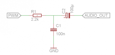
By default, the Auduino outputs a PWM-signal between 0 and 5V. We want to adapt this down to line level, which according to the web is between -0.5V and 0.5V. So it needs some kind of filter and pad on the output. We put together something simple with only 3 parts. See the circuit below | |||
{| | |||
| [[File:Arduino PWM Audio Filter.png|400px|thumb|PWM to Line level audio filter]] | |||
|} | |||
'''Note:''' Dave from [http://www.notesandvolts.com/2015/04/build-auduino-granular-synth-line-level.html Notes And Volts] has done some further optimization on the filter: [http://www.notesandvolts.com/2015/04/build-auduino-granular-synth-line-level.html Build the Auduino Granular Synth - Line Level Upgrade] | |||
=== Headphone out === | |||
Add a headphone output to the line output. | |||
== Versions == | |||
=== v0 Breadboard Prototype === | |||
First version, using fullsize Arduino Clone, and some potentiomenters on breadboard. Used it to try out different filters for the PWM signal, as well as some software mods. [http://log.munichmakerlab.de/post/90685187070/testing-arduino-synthesizer-for-annoyence-factor Picture] | |||
{| | |||
|[[Image:Auduino00.jpg|thumb|200px|First prototype]] | |||
|} | |||
=== v1 on perfboard === | |||
Version on perfboard in a "case". Built using an Arduino Pro Mini 5V 16Mhz. Has 5 CV inputs (3.5mm jacks), and audio filter built in. [http://tiefpunkt.tumblr.com/post/93669646067/last-night-i-put-a-prototype-of-the-auduino-synth Post on Tumblr] | |||
{| | |||
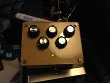
|[[Image:Auduino01.jpg|thumb|200px|The whole thing from the top]] | |||
|[[Image:Auduino02.jpg|thumb|200px|Protoboard from top]] | |||
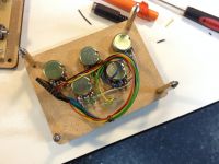
|[[Image:Auduino03.jpg|thumb|200px|Frontpanel from the back, with connector]] | |||
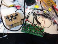
|[[Image:Auduino04.jpg|thumb|200px|Running the synth with a simple sequencer]] | |||
|} | |||
The pictures are missing the switch to select the scale, which was added a little later. | |||
== Links == | == Links == | ||
* [http://code.google.com/p/tinkerit/wiki/Auduino | * [http://code.google.com/p/tinkerit/wiki/Auduino Auduino Homepage] | ||
* [https://learn.sparkfun.com/tutorials/build-an-auduino-step-sequencer/all#understanding-the-framework Audoino Step Synthesizer] (includes a good explaination of what's actually happening inside the synth) | * [https://learn.sparkfun.com/tutorials/build-an-auduino-step-sequencer/all#understanding-the-framework Audoino Step Synthesizer] (includes a good explaination of what's actually happening inside the synth) | ||
[[Category:Project]] | [[Category:Project]] | ||
Latest revision as of 18:30, 25 June 2020
| Auduino Release status: beta [box doku] | |
|---|---|
| |
| Description | Simple Arduino based synthesizer |
| Author(s) | tiefpunkt |
| Download | https://github.com/tiefpunkt/Auduino |
The Auduino is a small synthesizer, based on the Arduino. The only external components required are 5 potentiometers, and something to output the sound, such as a small speaker, or a headphone jack.
Hacks
Modify the scale
By default, the Auduino uses a pentatonic scale. That can be changed in the source. An external switch to change the scale during runtime would be awesome.
Below are the options, only one is executed during runtime.
 // Smooth frequency mapping
 //syncPhaseInc = mapPhaseInc(analogRead(SYNC_CONTROL)) / 4;

 // Stepped mapping to MIDI notes: C, Db, D, Eb, E, F...
 //syncPhaseInc = mapMidi(analogRead(SYNC_CONTROL));

 // Stepped pentatonic mapping: D, E, G, A, B
 syncPhaseInc = mapPentatonic(analogRead(SYNC_CONTROL));
Adding some if-clauses, dependend on digitial inputs might be a decent solution.
Delay
Here's an example on using a ring buffer as a delay: http://rcarduino.blogspot.de/2012/11/auduino-with-delay.html
Maybe that could be added as an option as well.
CV Inputs (for sequencers)
CV Inputs are now done using 3.5mm jacks with integrated switches. They are placed between the potentiometers and the analog inputs of the Arduino. When a plug is inserted, the potentiometer gets disconnected from that particular input.
Next steps are to add some input over-voltage protection in the form of zener diodes, and maybe a possibility to use 0-10V CV.
A gate input would be great as well.
Adapt the Scales to 1V/Octave
On "old" analog synth hardware, 0-10V CV was used, with 1V/Octave. Not sure if the current scale reflects that, but it would be cool if it did, otherwise it might be wise to adjust this. However, in our case it would have to be 0.5 V/Octave
Line Level Output
By default, the Auduino outputs a PWM-signal between 0 and 5V. We want to adapt this down to line level, which according to the web is between -0.5V and 0.5V. So it needs some kind of filter and pad on the output. We put together something simple with only 3 parts. See the circuit below
Note: Dave from Notes And Volts has done some further optimization on the filter: Build the Auduino Granular Synth - Line Level Upgrade
Headphone out
Add a headphone output to the line output.
Versions
v0 Breadboard Prototype
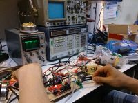
First version, using fullsize Arduino Clone, and some potentiomenters on breadboard. Used it to try out different filters for the PWM signal, as well as some software mods. Picture
v1 on perfboard
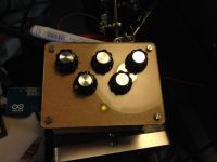
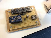
Version on perfboard in a "case". Built using an Arduino Pro Mini 5V 16Mhz. Has 5 CV inputs (3.5mm jacks), and audio filter built in. Post on Tumblr
The pictures are missing the switch to select the scale, which was added a little later.
Links
- Auduino Homepage
- Audoino Step Synthesizer (includes a good explaination of what's actually happening inside the synth)
