24V 18650 LiIon Battery System: Difference between revisions
(Created page with "{{project |name = 24V Modular 18650 LiIon Battery System |status = beta |image = 24v_liion_battery_system.jpg |description = Modular 24V litium ion battery s...") |
No edit summary |
||
| Line 11: | Line 11: | ||
== Introduction == | == Introduction == | ||
This battery system | This battery system consists of one or several ''battery cell holder modules'', a ''battery management system module'' to charge the cells with surplus energy and protect the cells from over- and under- voltage. Optionally a state of charge display module shows the voltage of each parallel cell string. | ||
=== Battery Cell Holder Module === | |||
Designed as a 24V battery, 7 batteries are wired in series (7s) and each of these consists of 2 cells which makes 14 cells per module. As the nominal voltage of a typical 18650 lithium ion cell is around 3.6V, 7 of them in parallel results in a nominal voltage of 25,2V. A typical end-of-discharge voltage is 2.8-3.0V making 19.6-21.0V in a 7s system. A fully charged cell usually has a voltage of no more than 4.2V, resulting in a maximum voltage of 29.4V for the whole battery system. | |||
=== Battery Management System Module === | |||
yet to come... | |||
=== State of Charge Display Module === | |||
yet to come... | |||
== Parts == | == Parts == | ||
| Line 22: | Line 31: | ||
1. Order PCBs, electronics parts, 18650 cells, cables, and screws | 1. Order PCBs, electronics parts, 18650 cells, cables, and screws | ||
2. Assemble 7s battery holder module | 2. Assemble 7s battery cell holder module | ||
3. Assemble battery management system module | 3. Assemble battery management system module | ||
4. Assemble current state of charge display module | 4. Assemble current state of charge display module | ||
Revision as of 13:45, 29 February 2020
| 24V Modular 18650 LiIon Battery System Release status: beta [box doku] | |
|---|---|

| |
| Description | Modular 24V litium ion battery system based on 18650 cells |
| Author(s) | Uli (Uli) |
| Last Version | 0.2.1 (28.02.2020) |
Introduction
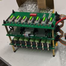
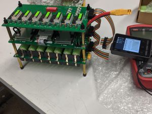
This battery system consists of one or several battery cell holder modules, a battery management system module to charge the cells with surplus energy and protect the cells from over- and under- voltage. Optionally a state of charge display module shows the voltage of each parallel cell string.
Battery Cell Holder Module
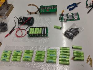
Designed as a 24V battery, 7 batteries are wired in series (7s) and each of these consists of 2 cells which makes 14 cells per module. As the nominal voltage of a typical 18650 lithium ion cell is around 3.6V, 7 of them in parallel results in a nominal voltage of 25,2V. A typical end-of-discharge voltage is 2.8-3.0V making 19.6-21.0V in a 7s system. A fully charged cell usually has a voltage of no more than 4.2V, resulting in a maximum voltage of 29.4V for the whole battery system.
Battery Management System Module
yet to come...
State of Charge Display Module
yet to come...
Parts
A complete bill of materials will be listed here shortly.
Housing
There is no design for a mobile housing or case yet, but it will be updated here, when there is one.
Assembly
1. Order PCBs, electronics parts, 18650 cells, cables, and screws
2. Assemble 7s battery cell holder module
3. Assemble battery management system module
4. Assemble current state of charge display module
5. Assemble and connect cables and wires
6. Test basic setup
7. Test battery under load
Debugging
yet to come
Open Issues
t.b.d.


