File:ErgoDash PCB Assembly.jpg
Jump to navigation
Jump to search

Size of this preview: 800 × 600 pixels. Other resolutions: 2,560 × 1,920 pixels | 4,032 × 3,024 pixels.
Original file (4,032 × 3,024 pixels, file size: 3.51 MB, MIME type: image/jpeg)
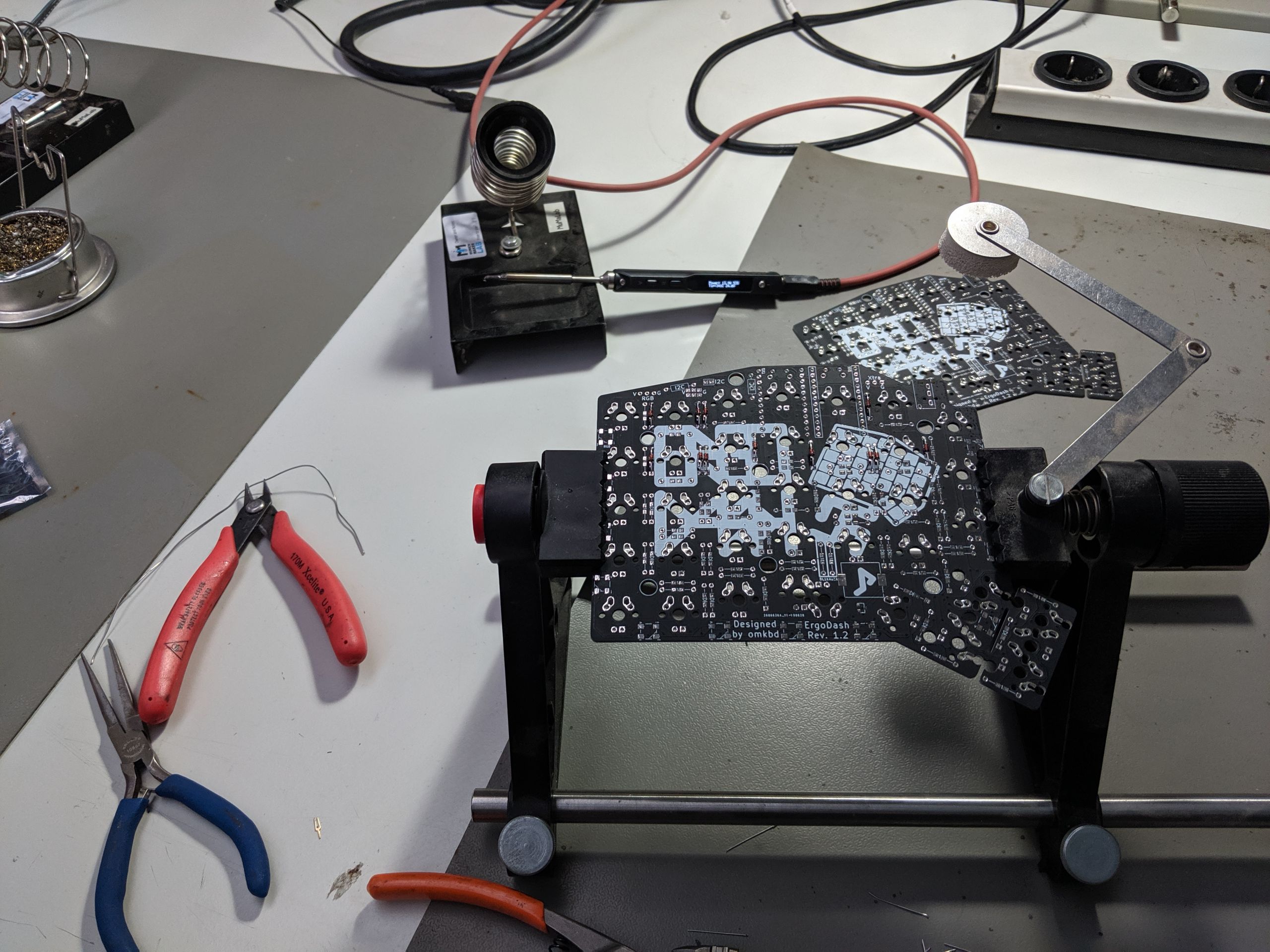
Summary
The electronics parts (mostly resistors and diodes) are being soldered onto the bottom side of the ErgoDash PCB
Licensing
File history
Click on a date/time to view the file as it appeared at that time.
| Date/Time | Thumbnail | Dimensions | User | Comment | |
|---|---|---|---|---|---|
| current | 12:32, 17 October 2019 | | 4,032 × 3,024 (3.51 MB) | Uli (talk | contribs) | The electronics parts (mostly resistors and diodes) are being soldered onto the bottom side of the ErgoDash PCB |
You cannot overwrite this file.
File usage
The following page uses this file: